
Detection and location of voids in the subsurface of mining and karst phenomena, which may cause the formation of discontinuous deformation on the surface,
- Determining the occurrence of aquifer,
- Determining the depth of occurrence of ceiling layers construction substrates,
- The term of the existing standards aggressiveness of the ground for cast iron and steel pipes,
- Determination of the routes of underground utilities (cables, pipelines,
- Detection and location of pollution.
GEOPHYSICAL RESEARCH SERVICES
Overview
Geocarbon offers range of geophysical survey services at highest quality possible and in numerous variations.
Microgravity
Introduction:
It is a noninvasive geophysical method that measures minute changes in the force of the earth’s gravity. Microgravity surveys are typically used to detect sub-surface cavities or changes in subsurface density.
Geocarbon’s employee at work

Method:
Changes in gravity measured at the earths surface reflect the underlying geological structure, hence the accurate determination of gravity leads to an understanding of the ground beneath. Microgravity surveys are used to identify lateral variations in the subsurface soil and rock density, which are influenced substantially by the size and depth of the target. The infield gravity, elevation, and time data are processed and a Bouger Gravity Anomaly map is produced. This map shows local relative gravity lows, which indicate areas of less dense materials located under the survey area.
Equipment:
CG-5 AUTOGRAV GRAVITY METER has a standard resolution of 1 microGal with the standard deviation that is < 5 microGals
CG-5 AUTOGRAV gravity meter
Application:
Cave & shallow hole detection
Coal mine working detection
Archaeological surveys (locating burial chambers and associated tunnels)
Geological mapping
Landfill studies
Regional gravity studies:
Aquifer monitoring
RIS MF Hi-Mod radar
Ground penetrating radar (GPR)
Introduction:
It is a noninvasive electromagnetic geophysical technique for subsurface exploration, characterization and monitoring.
Method:
GPR sends out an electromagnetic pulse which is reflected from a “target” and returns to the receiver. This reflection is detected by the GPR antenna and shows the location and shape of the subsurface objects and features. The antenna is pulled along the ground surface to produce a continuous subsurface profile. Data processing is carried out using specialized interactive software to optimize survey results. Data interpretation procedures correlate reflections on the GPR record with real physical interfaces such as soil or rock layering, voids, foundations and archaeological structures.
Unshielded 150 MHz borehole antenna
Equipment:
RIS MF Hi-Mod #4 is the IDS top level product dedicated to underground utility network mappings – 4 dual frequency (200+600MHz) antennas allowing a regular grid of both frequencies
Shielded 80 MHz antenna
Unshielded 150 MHz borehole antenna
GRED 3D Utilities software for easy data processing, creating tomographic maps and 3D views of underground utilities
Application:
Detects buried voids & cavities
Determines depth of bedrock and overburden thickness
For stratigraphic mapping, GPR can be used to map fill boundaries, shallow bedrock, and other shallow stratigraphy
Locating underground storage tanks, pipes, utilities, trenches, and other buried materials
Locating buried foundations and other obstructions
Tracks non-metallic culverts and sewers
Maps extent of ancient landfills
For archeological investigations
ERT/ERI
Introduction:
Electrical resistivity tomography (ERT) or electrical resistivity imaging (ERI) is a noninvasive multielectrode profiling technique for imaging sub-surfaces structures from electrical measurements made at the surface.
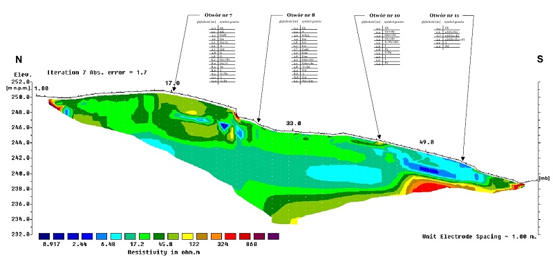
RT / ERI research method example
Method:
The survey data is processed using specialist inversion software to produce graphic depth pseudo-sections of the thickness and resistivity of subsurface electrical layers. The resistivity sections are correlated with ground interfaces such as soil and fill layers or soil-bedrock interfaces, to provide engineers with detailed information on subsurface ground conditions.
Enhanced data quality and resolution provide continuous two-dimensional resistivity models. Several dozen electrodes are set-out in a regularly spaced array, connected to a computer-controlled resistivity meter via multi-core cables. Unit electrode spacing is determined by parameters that include profile length, desired resolution and targeted depth penetration. A switching unit takes a series of constant separation readings along the length of the electrode array. The separation between sampled electrodes is then widened to increase the effective depth penetration and the procedure is repeated.
ERT / ERI research equipment
Application:
Measures bedrock & water table depth
Identifies fracture zones & discontinuities
(faults).
Detects solution features & voids (cavities)
Characterizing landslides
Maps contamination plumes
Characterizing landfills
Defines saline groundwater incursions
Archeological investigations
Locates buried alluvial channels
Finds abandoned mineshafts & workings
PET
Introduction:
The PET (Pile Echo Tester) uses the Pulse-Echo method for quick quality control of a large number of piles. The pile top is struck with a lightweight handheld hammer. The reflected wave is captured and analyzed by the PET’s digital accelerometer to provide information regarding the length and shape of the pile.
USB PET
Method
In the Sonic test, the top of the pile is tapped with a lightweight plastic hammer and the reflected wave are recorded by a suitable computerized equipment. From the resulting signal, or reflectogram, one can determine both length and continuity of the pile. In its most basic form, the sonic test measures the time between the hammer trigger, and the reflected wave, to indicate the pile’s length.
Performance
Pile lengths – 2 m to 100 m (depending on diameter and soil profile)
Productivity – Up to 100 piles/hour by single operator (under favorable conditions).
Sample test (reflectogram)
Capabilities:
Since the sonic method is based on the use of stress-waves, it can identify only those pile attributes that influence wave propagation. The following items may in many cases be detected:
- Pile length
2. Inclusions of foreign material with different acoustic properties
3. Cracking perpendicular to the axis
4. Joints and staged concreting
5. Changes in cross section
6. Distinct changes in soil layers
Inclinometering
Introduction:
Vertical inclinometers are instruments for measuring relative horizontal displacements affecting the shape of a guide casing embedded in the ground or structure. Inclinometer probes usually measure displacements in two perpendicular planes. Therefore displacement magnitudes and directions (vectors) can be calculated.
Inclinometer
Method
The bottom end of the guide casing serves as a stable reference (datum) and must be embedded beyond the displacement zone. Relative displacement over time is determined by repeating Measurements at the same depths and comparing data sets. The guide casing is installed vertically for most applications in order to measure horizontal ground movements.
Sample
Applications
Monitoring slope stability
Monitoring retaining structure performance
Monitoring excavations near facilities
Monitoring pile and drilled pier performance
Monitoring settlement of embankments
Monitoring deformation of pavement base
Monitoring performance during tunneling